Six fixed inputs must agree before one TV-wall box coordinate is safe: the television, mount, factory cord, connectors, finished wall, and service position. Miss one, and concealed connections can become inaccessible after the living room wall is finished.
A dimensioned TV-wall elevation should be completed before electrical rough-in
A reliable TV-wall rough-in starts with a dimensioned elevation tied to the exact equipment and finished surfaces, not a generic outlet height.
What must a TV-wall elevation show before drywall closes?
Use the finished floor as the vertical datum and the finished wall surface as the depth reference. Include paneling, tile, slats, and other applied finishes.
- Screen perimeter, TV model, overall dimensions, VESA pattern, power inlet, input panel, and ventilation restrictions
- Mount model, wall plate, rails or arms, fastener points, movement envelope, and collision zone
- Stud centers, blocking, load-bearing attachment points, and prohibited drilling areas
- Box cutouts, conduit endpoints, cable paths, cabinet top, service zones, and soundbar position
State whether each coordinate identifies a box center, cutout edge, or faceplate edge. If the wall borders a damp cavity or shows condensation, correct the moisture before closure. The U.S. Environmental Protection Agency advises fixing wet or damp spots promptly to prevent mold growth.
Which living room design decisions must be frozen before TV-wall rough-in?
Approve exact model numbers, wall thickness, cabinet dimensions, and source-equipment locations. First, lock the living room layout before TV-wall rough-in. Name one person to approve the coordinated elevation for the owner and trades.
For a covered commercial lounge, the 2010 ADA Standards set accessible dining and work surfaces at 28 to 34 inches above the finished floor. That range is not a TV-outlet rule. The upper outlet still must be positioned from the TV and mount drawings.
The outlet behind a wall-mounted TV must clear the mount and remain accessible
The upper outlet belongs behind the television but outside the mount’s rails, arms, fasteners, pivots, and crush points. Set its coordinates from the selected TV and mount, not from screen center or a universal height.
The outlet behind a wall-mounted TV must clear the mount and remain accessible shown with practical accessibility cues.
Where should the outlet sit behind the exact TV and mount?
Overlay the TV rear-panel drawing and mount drawing at the chosen VESA position. Mark the wall plate, rails, fasteners, tilt hardware, inputs, and power inlet. The remaining clear area must fit the box, faceplate, plug body, cord exit, and enough hand clearance to disconnect power.
Illustrative example only: One project might place the receptacle center 8 inches right and 6 inches below screen center after the overlay confirms clearance. Those coordinates apply only to that TV, bracket, plug, and finished-wall plane.
| Mount | Collision zone | Cord slack | Access test | Failure to avoid |
|---|---|---|---|---|
| Fixed | Rails and fasteners | Short, relaxed loop | Reach plug before hanging | Plug crushed by chassis |
| Tilting | Rails and tilt hardware | Slack through full tilt | Remove plug at service angle | Cord trapped at pivot |
| Full-motion | Folded arms and pivots | Slack through extension and swivel | Reach plug when extended | Repeated pulling or pinching |
A full-motion TV mount requires a larger cord and box clearance zone
Move the mount through its full extension, swivel, tilt, and folded positions. Watch for tension, connector loading, and contact with the receptacle. A captive cord needs movement slack; a detachable cord also needs space around its connector shell.
Lower TV-wall connections should align with the equipment cabinet and service path
Set lower coordinates from the cabinet height, back openings, shelves, baseboard, ventilation space, and service approach. Count every power, network, coaxial, audio, and video termination before sizing the pathway.
Commercial accessibility planning may also require the ADA Standards’ 30-by-48-inch clear floor space for wheelchair positioning. That requirement does not determine the residential TV outlet location. Confirm receptacle accessibility with the electrician and inspector, then select a recessed assembly suited to the wall.
A recessed TV connection box must match the wall construction and listed use
A recessed box is suitable only when its listed configuration provides adequate cavity depth, connector clearance, conductor arrangement, and service access.
| Option | Suitable use | Primary risk |
|---|---|---|
| Recessed receptacle | Moves the TV plug into the cavity | Plug or cord still collides with the mount |
| Divided combination box | Groups power and data using a listed barrier | Incorrect divider or conductor routing |
| Pass-through plate | Routes approved communications cable | Power cord concealed through the wall |
| Listed in-wall power kit | Relocates power as a complete approved system | Substituted or incorrectly installed components |
When is a recessed receptacle better than a standard receptacle?
Choose a recessed receptacle when the projection of a standard receptacle, plug shell, and cord bend exceeds the measured TV-to-wall clearance. Recessing power does not correct insufficient cord reach, blocked signal ports, or interference from mount rails.
When should a listed in-wall TV power kit be used?
Use a listed in-wall power kit when an approved complete system must carry power between an accessible source receptacle and the TV location. Verify the exact certification record, permitted cable, inlet, receptacle, orientation, wall construction, and installation instructions. Do not combine parts from unrelated systems.
Wall panels and thick finishes change recessed-box depth
Coordinate wall panels before setting recessed-box depth. Record the total finish thickness, then verify box setback, extensions, faceplate seating, fastening method, cavity depth, and removal clearance.
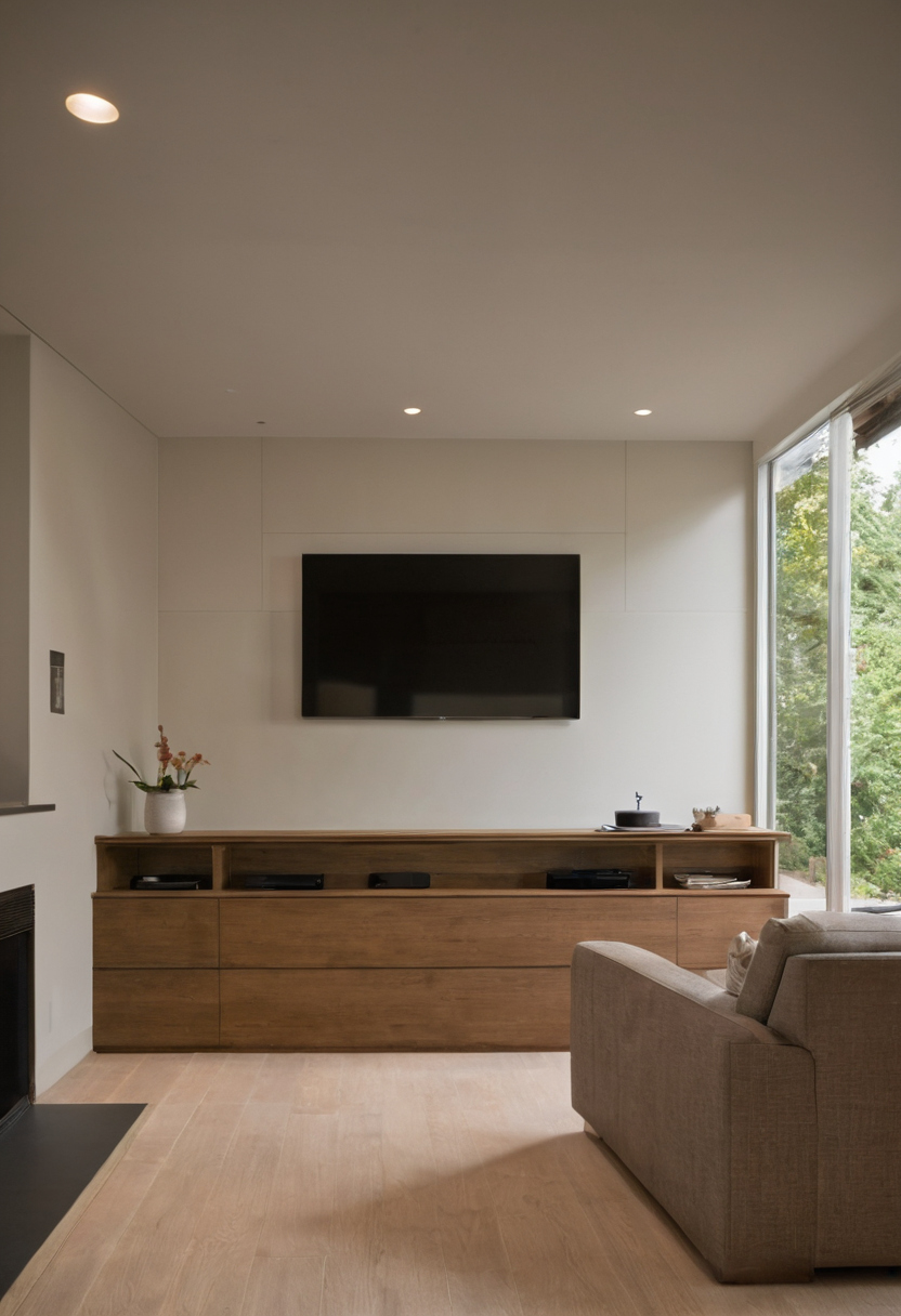
A recessed TV connection box must match the wall construction and listed use shown as a planning reference for layout, scale, and material decisions.
Preserve rated assemblies with approved penetrations and restoration methods. During installation of emitting finishes, follow the EPA recommendation to increase ventilation. Once the box fits the construction, test the real cord path.
TV cord reach must be tested in mounted and service positions
Cord reach must be proven with the television in its viewing and service positions, not estimated from screen size or straight-line distance.
How do you verify that the factory TV power cord reaches the outlet?
- Confirm whether the factory cord is captive or detachable and record its plug orientation.
- Measure usable length from the device inlet to the plug face, excluding the inlet strain relief that cannot bend.
- Route a cord or tape around the actual rails, arms, cable clips, and strain-relief points.
- Move the mount through every viewing, tilt, swivel, folded, and extended service position.
- Confirm that the plug inserts and releases without pulling on the TV inlet or entering a hinge.
Connector depth and bend radius must fit behind the mounted TV
Measure from the finished wall plane to the nearest TV chassis surface. Subtract the faceplate projection, plug body, connector shell, and required cable turn. Check the actual HDMI, Ethernet, coaxial, optical, USB, and power connectors because shell dimensions and exit directions vary.
Follow each cable manufacturer’s bend and handling limits. Use angled adapters only when permitted by the connected equipment and cable instructions. Passing the reach test leaves one more constraint: the concealed pathways must comply with the adopted code.
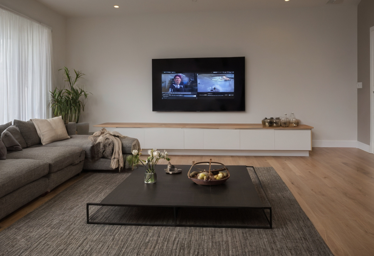
TV cord reach must be tested in mounted and service positions shown with floor, wall, and fixture relationships visible.
TV-wall power and communications wiring must follow the adopted code and product instructions
TV-wall wiring must follow the electrical code adopted for the project address, local amendments, cable markings, and listed equipment instructions. Flexible appliance cords and ordinary extension cords are not concealed building wiring.
| Rough-in item | Approval basis | Failure to avoid |
|---|---|---|
| Upper receptacle | Adopted code, box instructions, and electrician review | Blocked access or missing protection |
| Power and data enclosure | Listed box, barrier, raceway, or complete kit | Unapproved mixing of wiring systems |
| Signal cable | Jacket marking and manufacturer limits | Unrated cable or excessive bends |
| Framing penetration | Structural and fire-resistance requirements | Damaged framing or open concealed paths |
Which electrical rules govern a living room TV outlet?
The project jurisdiction determines the adopted NFPA 70 edition, amendments, permit process, and inspection requirements. Adoption changes over time. The Connecticut Department of Administrative Services reports that proposed 2026 codes anticipate the 2023 NFPA 70 edition, but approval has been delayed. The new codes will apply based on permit timing after their effective date, so that proposal does not identify the edition governing a current project.
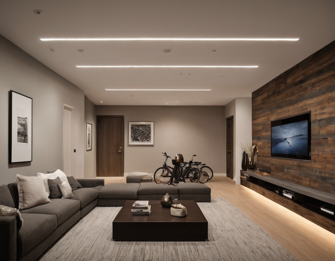
TV-wall power and communications wiring must follow the adopted code and product instructions shown as an editorial reference for proportion and finish coordination.
The dwelling-unit provisions commonly summarized as the 2-6-12 rule address general receptacle coverage along qualifying wall spaces. They do not set the mounting height for an additional TV receptacle. The electrician must verify AFCI protection, any location-triggered GFCI protection, conductor protection, box position, and acceptable access.
Power and low-voltage wiring may share a TV-wall area only through approved methods
Power and communications wiring may occupy the same area only through arrangements permitted for their classifications. Use the listed divider, separate enclosure, raceway, conduit, or spacing method specified for the products. Do not invent a universal separation distance.
Only cable marked for the intended in-wall use should enter the concealed pathway
Every concealed cable needs markings appropriate to the cavity, raceway, riser, plenum, or rated assembly involved. Follow pull-tension, bend, support, and termination limits. The EPA identifies paints, varnishes, building materials, and furnishings as common indoor VOC sources, but material ventilation guidance does not replace electrical approval. The final safeguard is an open-wall inspection.
The TV-wall rough-in should pass a documented pre-drywall inspection
Before wall closure, photograph, measure, label, and test the rough-in against the approved elevation, equipment schedule, product instructions, and adopted code.
What should be checked before the TV wall is closed?
- Confirm TV, mount, soundbar, cabinet, and box model numbers.
- Record box and conduit coordinates from the finished-floor datum.
- Photograph studs, blocking, boxes, pathways, and obstructions with a tape visible.
- Check box depth against the complete finished-wall plane.
- Verify conduit continuity, pull strings, bend condition, and cable labels.
- Test installed signal and data cables with suitable tools.
- Record firestopping, electrical inspection status, corrections, and approval.
Mark every field deviation on the elevation and obtain approval from the responsible owner, designer, AV installer, electrician, or contractor. Do not authorize wall closure while a deviation affects access, structure, wiring, or inspection.
A dry-fit should confirm TV plug access before final installation
After the finish is installed, use the approved template or safely dry-fit the mount and connection hardware. Each plug must insert and release without removing fixed trim. Tilting and full-motion mounts must travel through their service positions without pinching connectors or loading cables.
Approve the TV wall only after the documented rough-in and finished-wall dry-fit both pass. That sign-off costs less disruption than finding an unreachable receptacle after the screen and wall finish are installed.
Frequently asked questions
Where should an electrical outlet be placed behind a wall-mounted TV?
Place it within the screen footprint but outside the mount, fasteners, moving arms, input panels, and ventilation zones. Derive the coordinate from the exact TV and mount drawings.
Where should the lower TV connection box go?
Align it with an accessible cabinet opening and the upper pathway while clearing shelves, drawers, baseboards, and ventilation space.
Is a recessed outlet or an in-wall power kit better?
Use a recessed receptacle for plug-depth clearance. Use a listed in-wall power kit only as a complete approved system when power must be relocated through a finished wall.
Does the 2-6-12 rule determine TV outlet height?
No. The rule concerns general dwelling-unit receptacle coverage along qualifying wall spaces, not the height of a TV receptacle.
Can an extension cord or detachable TV cord be hidden inside the wall?
Do not conceal an ordinary extension cord or appliance power cord as permanent wiring. Provide a code-compliant receptacle, fixed wiring method, or listed in-wall power system approved for the installation.